DISCLAIMER: The modifications described in the following text are for educational purposes only. In no way do we recommend that you apply these modifications to your own motorcycle. If you do choose to go ahead and modify your motorcycle based on the information in this document you will accept all responsibility for your own actions. The author(s) of this document, and host(s) providing it for you, accept no responsibility whatsoever. If you are unqualified to make any of the changes described herein but are bent on doing the modification, seek out a knowledgeable friend or professional mechanic for assistance.
Rebuilding the rear shock absorber on a Yamaha TTR250
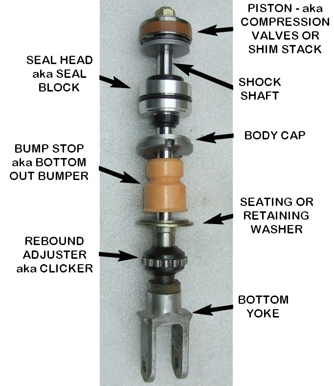
The TTR250 shock is very hard wearing and usually will last the lifetime of the bike. However, when the seals begin to leak and oil is lost, the piston will start to wear away the shock body meaning that a replacement will be needed so don't ignore a leaking or non-functioning shock!
This pictorial guide assumes you have removed the shock absorber, thoroughly cleaned it (preferably by power washing) and have it on the bench ready for action and that you are on a budget and you need to get your shock working again asap!
Tools needed:- Large-headed Phillips screwdriver, small plain screwdriver or pick, hammer and punch, 12mm and 17mm spanners or sockets and a large cable tie. A soft-jawed vice firmly attached to a workbench would be ideal!
Parts/supplies: Seal head and shock oil. New bump stop if required. Approx 400ml of fork oil 2.5W-7.5W (preferred) or ATF. Football inflator needle or nitrogen shock needle to de-pressurise the shock before dismantling. Drill and tap to fit Schrader valve to reservoir if not using the nitrogen needle. All parts are available from Totally TTRs.
To make sure you have what you need to hand so that you can do the job in one hit, a decision needs to be made before you start about how you are going to pressurise the shock after its rebuild. There are a few choices:
IMPORTANT advice from a TTR250 owner who has re-gassed and changed fluids in
hundreds of Fox snowmobile shocks with air and transmission fluid:
You don't need nitrogen as air will work fine - the air we breathe is 78% nitrogen in any case. In the TTR250 shock, the gas (nitrogen or air) is separated from the oil.
Transmission fluid or power steering fluid (ATF) will work fine in shocks or forks. It is cheap, seal friendly, and won't foam. Use the thinnest you can lay your hands on.
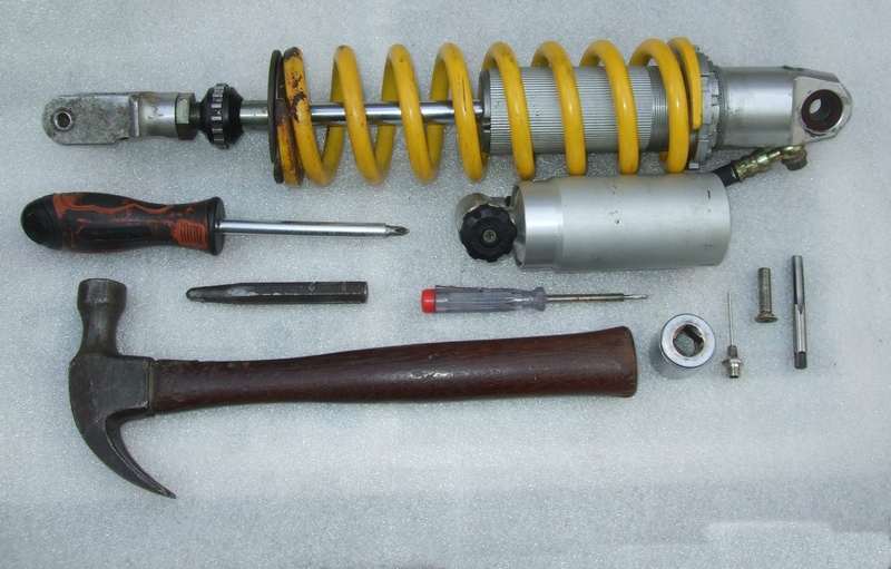
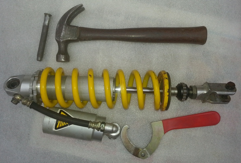
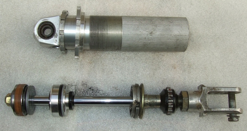
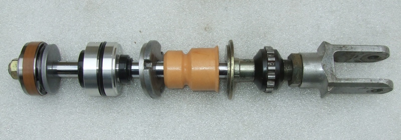
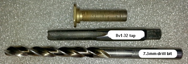
It's worth taking a photo of your shock before disassembling it so that you can get an idea of the settings when you re-assemble it e.g. how far down the spring adjuster rings sit. The following photo illustrates the tools that you may need in addition to a decent vice. The original bump stop had disintegrated hence there isn't one in the photo! NB A good tip is to lay out all parts in order as they are removed so that they can more easily be kept track of.
PS It is always easy to be wise after the event but we also needed 12mm and 17mm spanners or sockets and a large cable tie!
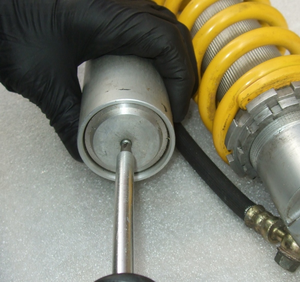
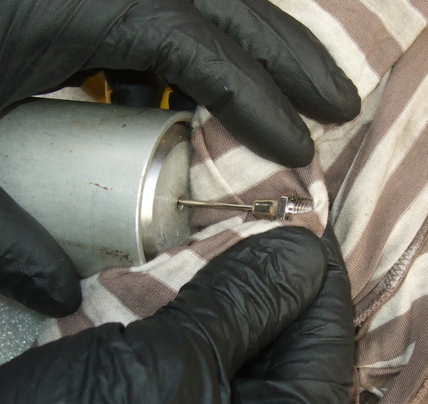
The first job is to depressurise the shock. Take out the 4mm screw from the bottom of the shock reservoir, grease up a hollow needle and insert it through the rubber pellet at the bottom of the hole to release any remaining pressure. Back out the adjuster knob fully (so that the orifice controlled by the needle is as large as possible to help cleaning out the oil ways) and remove it to prevent any possible damage.
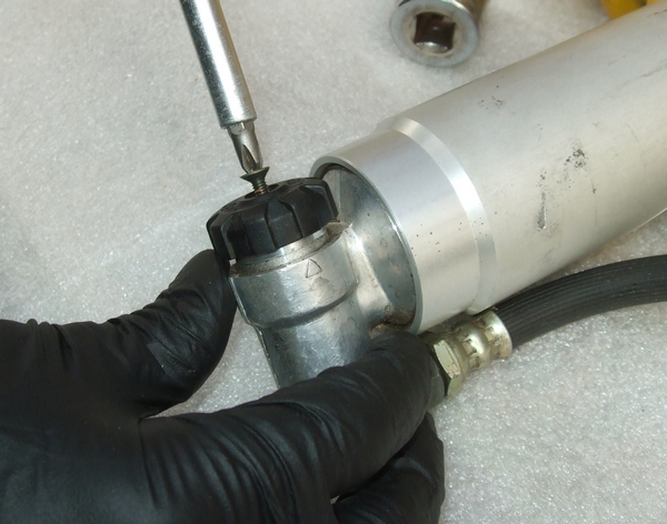
Push the reservoir cap down just far enough to allow you to use a small screwdriver to remove its wire circlip. It is easier to do this in the vice using a socket pushing down against the cap.
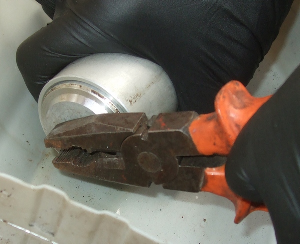
Replace the screw to allow you to get a pair of pliers on it to pull out the cap. It'll need a bit of wiggling to get it out. Remove it, along with the rubber diaphragm, over a pan to catch the oil.
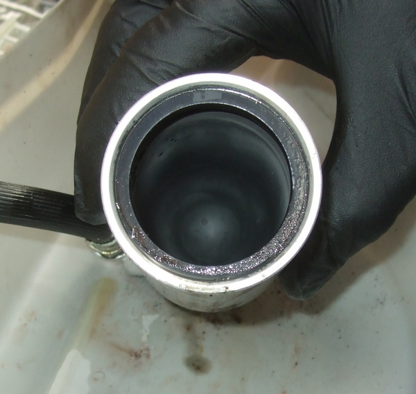
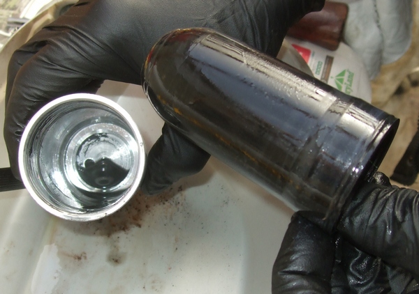
Remove the 12mm banjo bolt that holds the reservoir to the shock body and let the oil drain out of the shock and reservoir. About 150ml of very dirty oil came out of this shock so not a lot.
![]()
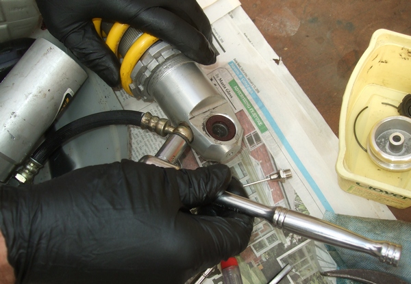
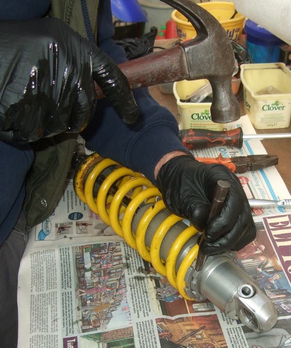
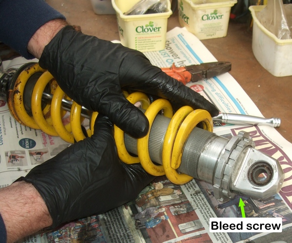
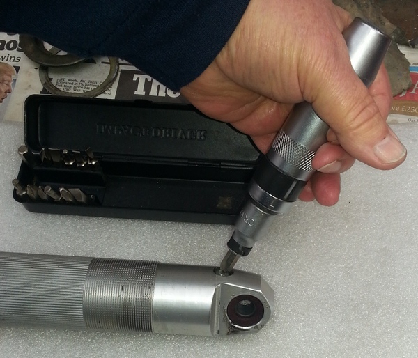
Wind off the shock rebound adjuster so that the valve is fully open. Loosen off the spring locking collars using a hammer and punch (a pre-load C spanner as shown in the photo below is available if you prefer!) and remove the spring and its keeper plate. If the collars catch on the large bleed screw such that they won't slide off then no matter as it is possible to remove the spring from the bottom of the shock. PS With the benefit of hindsight, the screw needs to be removed to bleed the shock at a later stage so we should have taken it out at this point in the dis-assembly.
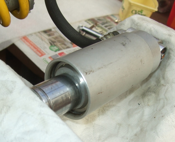
Put the shock in a vice with shaft up, take a thin screwdriver and pry up the press-fit shock body cap. On this shock it was very tight so it had to be loosened in the vice before it would come off.
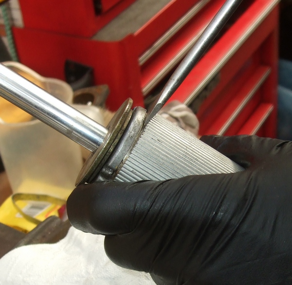
Push the shock shaft into the shock body and remove the retaining circlip. Clean inside and then, over a drain pan, pull on the shock shaft to remove the complete assembly. Drain any remaining oil.
Loosen the bleed screw if not already done and re-tighten against its O ring sufficiently to get a seal You will need to be able to remove it to bleed the shock body later! This one was very tight so an impact driver was needed to loosen it.
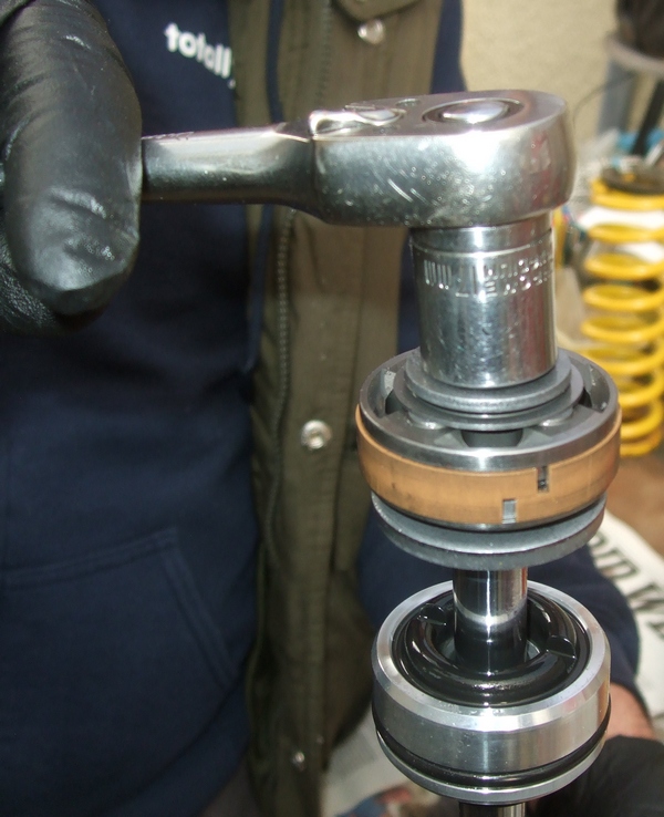
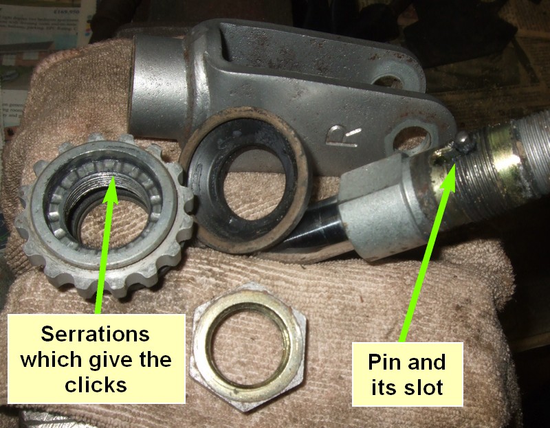
With the shaft in the vice (end nut up), unscrew the 17mm nut and remove the shim stack keeping the parts in order on a metal rod or a cable tie. also remove the old seal head which can be discarded as it will be replaced by a new one.
As oil passes through the piston, the shims bend and valve stacks open so it's important that they are clean so that they can function correctly.
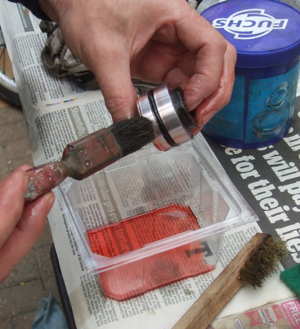
Swill the stack around in cleaning fluid such as petrol before setting the parts out in order on a clean surface such as newspaper or a paper towel.
![]()
![]()
The piston has a bushing which fits around it and an O ring underneath it. Be very careful to clean these without damaging them as, to date, replacement parts have not been identified.
Even after swilling off the stack, you will see dirt on the individual shims that needs to be cleaned off else it will stop the shim stacks working properly.
![]()
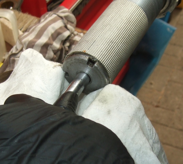
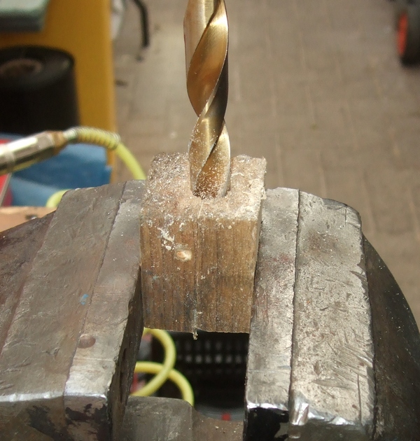
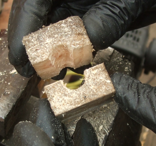
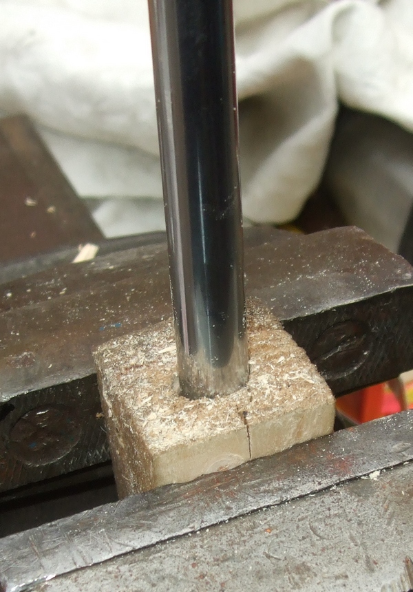
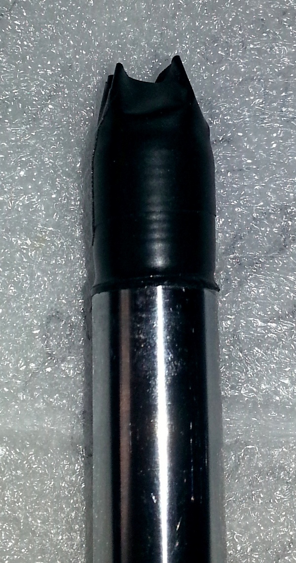
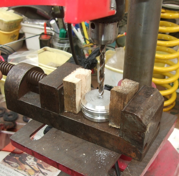
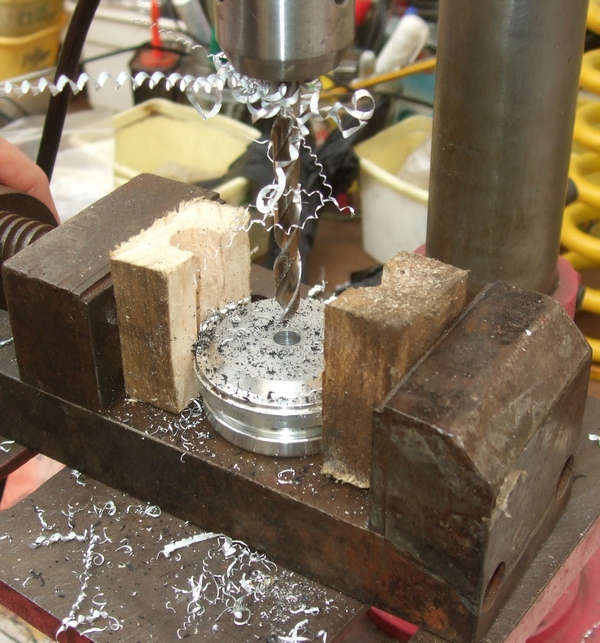
When undoing the nut on this shock absorber, the shock shaft unscrewed from the bottom yoke assembly so a wooden clamp was quickly made up to grip the shaft in the vice without damaging the chrome. It was about an inch square and nearly two inches long with a 13mm hole drilled through the middle. The block was then cut in half as shown in the photos below. It doesn't need to be precise as you can see in the photos! Grip the shaft as near to the bottom as possible, preferably where the bump stop normally sits - just in case! Any damage to the chrome there will not affect the seal head.
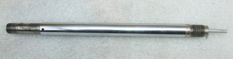
The shock shaft needs to be checked as the seal head slides up and down on it and any rough parts could damage your new seal head. Any minor imperfections can be removed carefully by lightly polishing the shaft with 800-1000 grit sandpaper and soapy water. Only polish perpendicular to the shaft and not parallel to the shaft as that would create micro leak paths for the oil to follow. NB It is quite common for rust to form under the bump stop but do not worry about that as any part of the rod below the body cap will not affect the seal head.
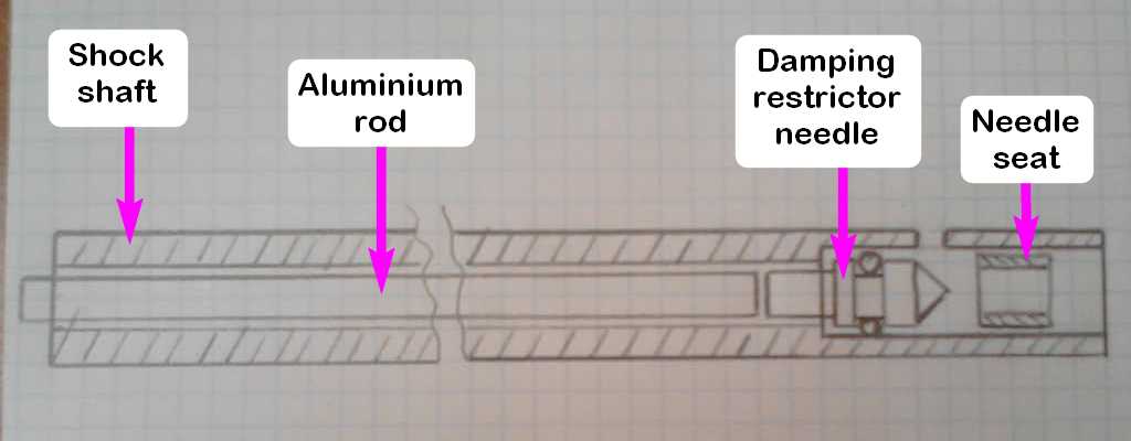
If you are unlucky enough to have your shaft damaged then Dynasurf offer a regrind/rechrome service for shock shafts. My brother-in-law's TTR250 shaft has a tiny area where the chrome had started to lift and the sharp edges tore into the seal head and he lost all his oil. He sent his shock shaft off to Dynasurf and they did a great job. Total cost (September 2022) was £80.33 (Carriage up £5.33 using Evri, carriage back £15.00, re-chrome £60.00) As new TTR250 shock absorbers are no longer available from Yamaha, and good second-hand shocks become harder to find, this will become a solution for owners.It is worth checking the operation of the "damping restrictor needle" whilst the shock shaft is clear of shims etc. This is easier to do than describe! Basically the rebound damping on the TTR250 shock is adjusted by the clicker at the bottom of the shock and works against an aluminium rod that goes up through the hollow centre of the shock shaft and pushes the needle against its seat . The rod gets pushed up to increase the damping force and down to decrease it.
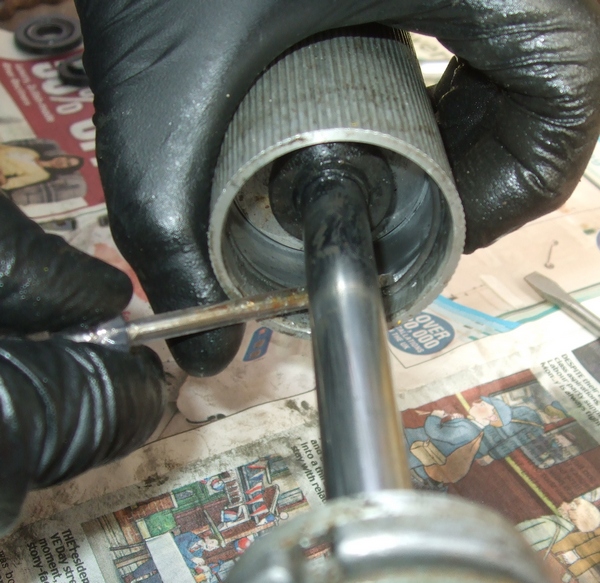
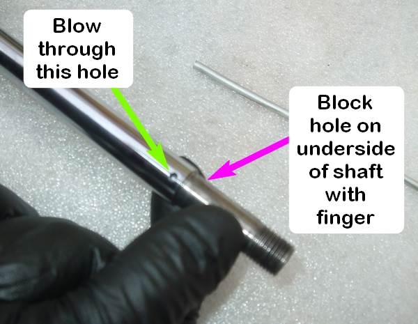
To check the needle is moving as it should, first push the rod firmly upwards from the bottom off the shock shaft. Put your finger over one of the oil holes and blow in the other. It should be sealed and no air escapes.
Next, push the rod (more carefully this time) in from the other end. Push it downwards against the point of the damping restrictor needle and you should feel a slight movement.
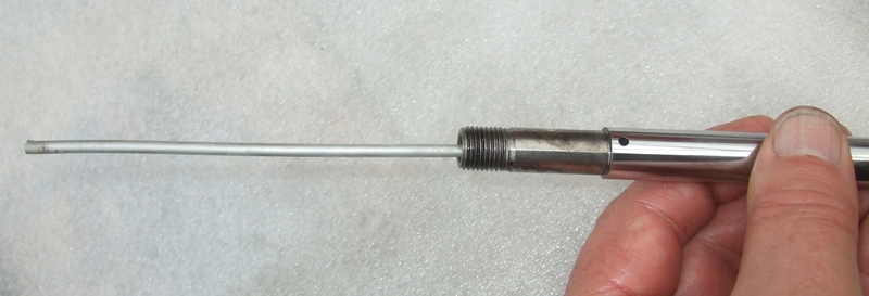
Do the blow test again and there should be no resistance and air should easily escape from the top of the shaft. If it does this then all is well and the needle is moving freely.
Strip out and clean and grease the clicker assembly at the bottom of the shock to make sure it is operating correctly and is not damaged.
Re-assembling the shock
To make the following tasks easier, put the aluminium rod inside the shock shaft and screw the shaft onto the bottom yoke assembly.
Slide on the small thick bottom spring washer (flat side downward as shown in the photo below) followed by the bump stop and then the shock body cap.
Oil the new seal head and the shock shaft. To make sure you don't damage the seal head O ring on the shaft threads or the sharp raised edge of the shaft, wrap insulating tape over the threaded shaft end and slide the seal head on. The tape can now be removed.
Next fit the pre-oiled valve stacks and piston. This is more easily done by putting the end of the rod or cable tie in the hollow end of the shock shaft and manoeuvring the assembly on over the end of the shaft. This way there is no danger of muddling up the shims. Oil the piston and fit the piston bushing and then the 17mm retaining nut.
![]()
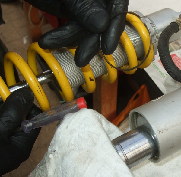
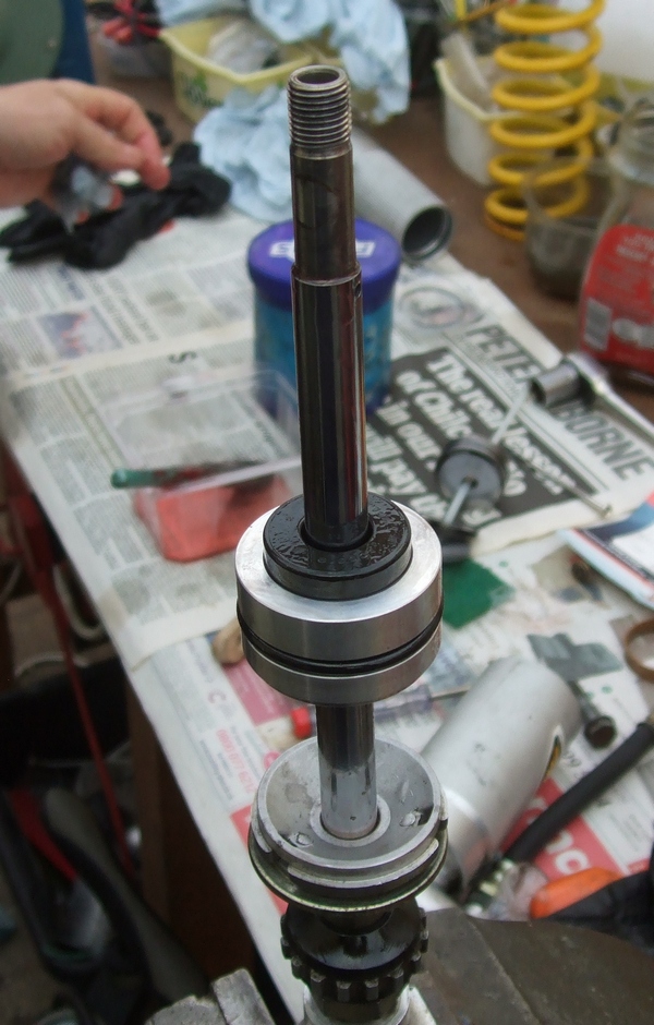
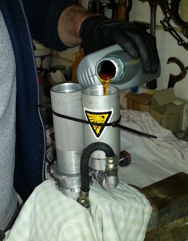
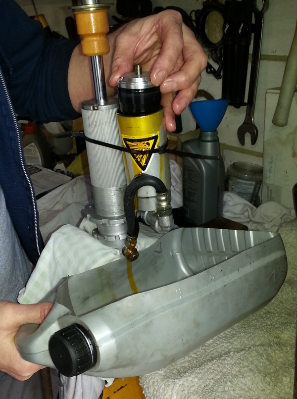
Refit the reservoir banjo bolt to the shock body and tighten the bleed screw in so the oil will stay on the inside! Put the shock body in the vice open end up and zip tie the reservoir to it as shown in the photo below. Fill the shock body with oil to within about 1/2" of the top and fill the reservoir about a third full.
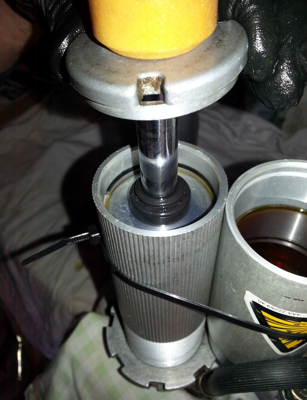
Push the shock shaft down into the oil and some of the oil will be pushed into the reservoir. Stroke the shock shaft up and down gently and you should see air bubbles escaping.

Fill oil to within an 1" or so of the top of the shock body and press the shock seal down past the circlip groove. More oil will be pushed into the reservoir. Fit the wire circlip and pull up on the shock shaft against it to make sure it is properly seated. Tap the body cap back into place.
Reassembling the reservoir.
There are two options for the home mechanic who doesn't have access to a professional nitrogen fill setup:
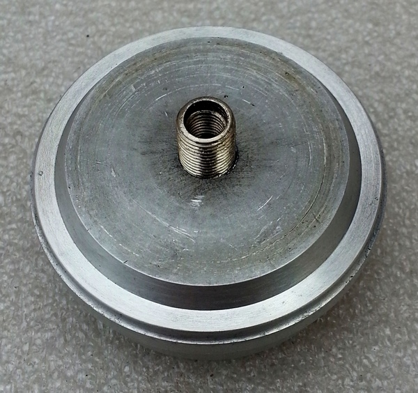
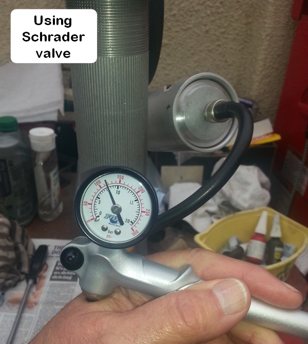
a) Adapting the reservoir cap to take a Schrader valve. This requires a 7.3mm drill, an 8v1-32 tap and a Schrader valve from an old inner tube.
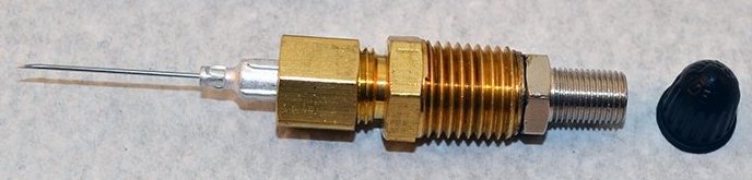
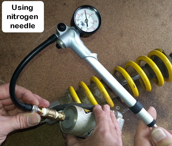
b) Use a nitrogen needle fill adaptor with a Schrader valve. The adaptor pressurises the shock through the self-sealing rubber plug/pellets
in the reservoir cap. It is combined with a Schrader valve tip, so it can be used with a standard air line or can be threaded directly into a no-loss MTB
hand pump to pressurise the shock. Cost about £30 plus delivery.
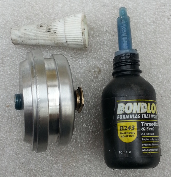
If going the Schrader valve route, use an old Schrader valve from an inner tube that has a good thread. Remove any rubber and hacksaw or file flats onto the end to assist in tightening it into the cap. Drill out the screw hole in the reservoir cap using a 7.3mm drill (don't try using a 7mm because the threads will bind - as we found out the hard way!). Thread the hole using the 8v1-32 tap - not a common thread! Clean off the swarf and screw in the Schrader valve from the inside of the cap using a good squeeze of thread locker/sealer to make it airtight. Refit the valve.
If going the nitrogen needle route, you can proceed directly to the next stage and refit the reservoir cap with bladder.
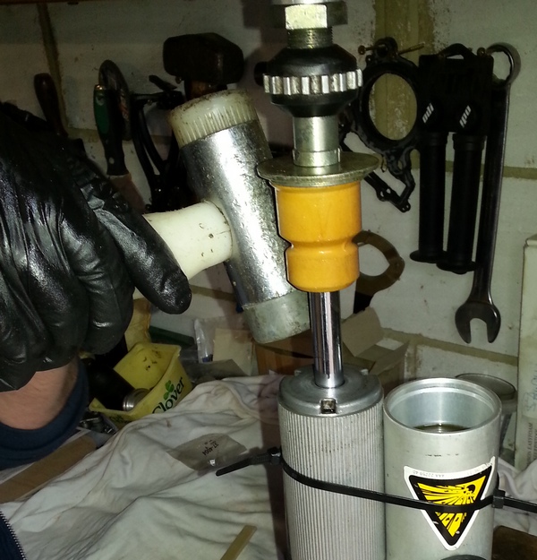
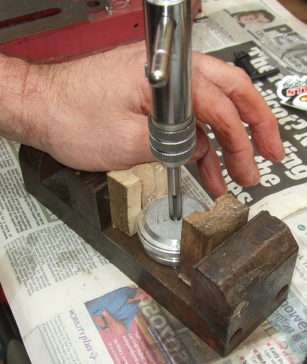
With the shock shaft pulled out fully, refit the bladder to the cap and push it down into the reservoir. Ideally, you want oil spilling over the top as you install it. Push the cap down past the circlip groove and fit the circlip. You will probably need to squeeze it in with the vice. We had fitted a Schrader valve so used a socket to sit over and protect it. In our case, the vice jaws wouldn't open far enough so we used a sash cramp as shown in the photo below.
To bleed out any of the remaining air, put the shock in the vice in the upright position. Carefully unscrew the bleed screw that is opposite the reservoir banjo fitting. This is the highest point for the shock. Pump the shaft a couple of millimetres slowly working out air bubbles keeping the shaft fully extended.
Replace the screw and move the shock around visualizing air bubbles rising towards the bleed screw. Sometimes air bubbles stick on internal surfaces so put the shock on the bench and give the top a few sharp taps with a hide/rubber/plastic hammer. Remove the screw and let out any air that might have gathered. Repeat until you have nothing but oil coming out of the screw hole, then replace the screw tightly.
You can now pump air into the reservoir bladder with 130 psi as a starting
point. The pressure in the bladder is just another shock tuning variable
but anything over 130 psi will allow the shock to function as designed. The more
pressure, the stiffer the ride so experiment! NB If you intend to check the
pressure in the shock, be aware that it will lose about 7psi due to gas in the
shock having to fill the gauge.
At this point both the damping and rebound valves should be fully open if the instructions have been followed. To test that the rebound valve is operating correctly, wind the clicker out to the standard setting of 9 clicks from the fully closed position. It should be possible to compress the damper rod and, once released, it should return quite quickly to the fully extended position. See here for a video demonstration of this.
If all looks good with no oil or air leaks then the spring can now be replaced. This is basically the reverse of the dismantling process.
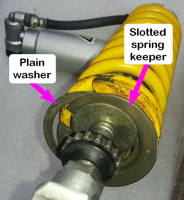
Fit the spring on from the bottom of the shock followed by the large plain washer and the slotted spring keeper.
Wind down the locking washers to their original position (making sure that the collar on the bigger washer is facing downwards to locate in the top of the spring) so that the sag will be the same as before the rebuild. Hold the lower lock washer whilst tightening the top one against it with a hammer and punch to lock them together.
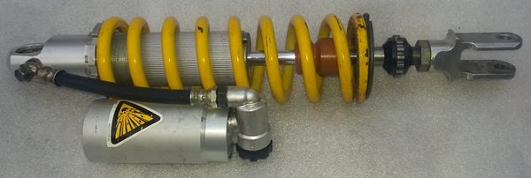
The shock is now ready to refit to your TTR - job done!
Steve Attfield and Brian Sussex
Compiled by Brian Sussex, Devon, UK
http://www.totallyttrs.com/
- everything you need (possibly!) for
your TTR250
http://www.ttr250.com/
- all you ever wanted to know
about TTR250s
http://ttr250.activeboard.com/
- the forum for TTR250 owners
http://www.totallywrs.com/
-
for all your WR250R and WR250X after-market parts and accessories
Reference within this site to any specific commercial or non-commercial product, process, or service by trade name, trademark, manufacturer, private individual or otherwise does not constitute or imply an endorsement, recommendation, or favour by Totally TTRs